Getting a Lift from FLAPS
We have discussed all the parts of an aircraft, Tommy to be exact, that help to control and balance an aircraft in flight. They all move in two directions. Controlled by the control stick or the rudder pedals. Now we will discuss the Wing Flaps and their use in both slowing Tommy down, and giving him the added “lift” he needs to slow down for a smooth, safe landing.
The FAA defines Flaps as “The hinged part of the trailing edge of the wing located between the Ailerons and the Fuselage. They change the lift and drag on the wing.”
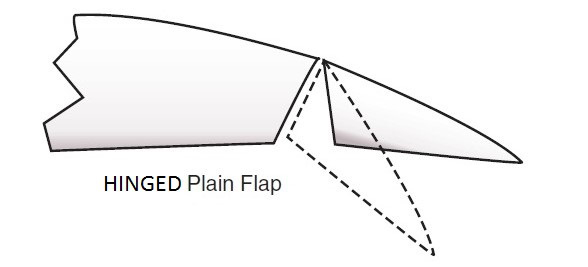
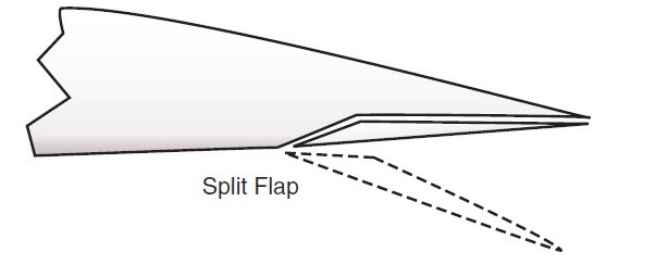
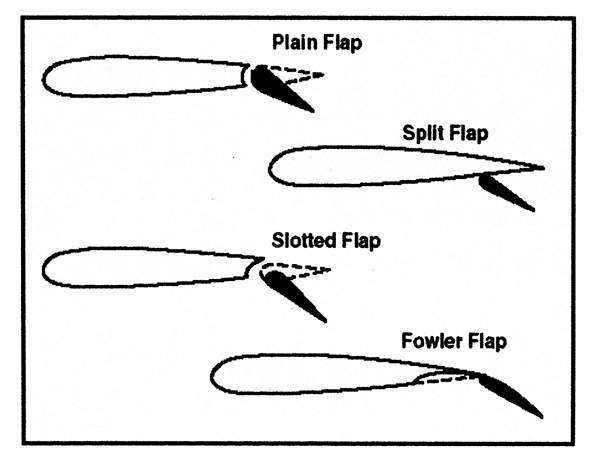
The flaps are a movable surface that pivot down into the slipstream and indeed have two functions. They help to slow down the aircraft while at the same time, by changing the airflow, change the lift produced by the wing. There are basically three different designs; Hinged, Split, and Fowler Flaps. Tommy has a unique design in that they are a Split-Hinged Design.
Hinged Flaps are a simple design and are hinged, just like the doors in your house. They move on a pivot point and lower down into the airstream, while altering the airfoil of the wing.
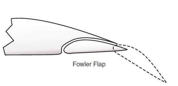
Fowler Flaps are designed to not only lower but will move rearward (back) changing the design and area of the wings’ airfoil. They are by far the most efficient design and are found on jet transports and many high-performance piston and turbo-prop aircraft.
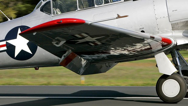
The flaps on Tommy are the Split-Hinged Flap design. The wing on a T-6 is split along the rear of the wing where the flaps are located. The top of the wing does not move. Only the lower part moves when flaps are selected. Tommy has three (3) flaps. One on each wing, and one that runs under the fuselage from where the outer wing connects to the center section. You can see where the center section is by noting the ridge along the wing. They are controlled from a lever in the cockpit on the left side control shelf area. The lever is labeled “Up-Off-Down.” There is a flap position indicator also located forward of the handle on the shelf. It is labeled “10-20-30-40” degrees.
Since the flaps alter the design and effectiveness of the wing of the aircraft, there is a speed limitation on their use. They cannot be used over 125 miles per hour on the T6 as it would over stress the flaps.
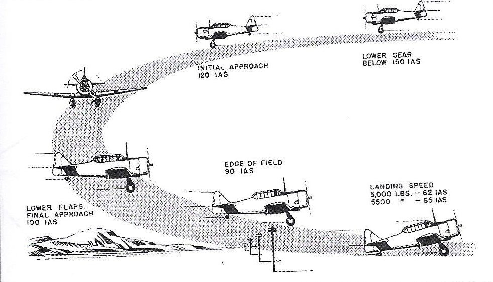
Once the pilot has entered the traffic pattern, see diagram below, the flaps are lowered as the pilot needs them on the base leg and then final flaps, or Landing Flaps, are selected on final approach.
When the flaps are lowered this may also cause a pitch change, since the design of the wing has been changed, causing the pilot to have to hold forward or aft pressure on the control stick, as we mentioned in Part 3, that can be controlled with the use of the Elevator Trim.
If you have any questions, email Captain Billy!